Describing scenes for the MPK path planner

Author: Sagar Behere Email: [email protected]

The MPK path planner module in the Sarathi framework needs a 'scene file' as input. A 'scene file' is a text file describing the environment in which the path planner operates. The environment consists of a robot and the obstacles in its workspace. The environment description thus consists of a description (including location) of the robot and the obstacles. This document explains how to create a custom scene file describing the environment of your application.

Introduction

The MPK scene file format is an extension of the Open Inventor scene file format. MPK extends the Inventor file format by three node types: mpkObstacle, mpkRobot and mpkIncludeFile. These are derived from the Inventor node type SoSeparator and can thus have the same attributes as a SoSeparator, in addition to their own specific attributes.

In this document, we will create a custom scene file to which we will add the KUKA KR5 Sixx R850 robot by using the mpkRobot node. Next, we will add obstacles, using the mpkObstacle and mpkIncludeFile nodes.

Quick Summary

  1. Open empty text file
  2. Add the line: “#Inventor V2.0 ascii” (without the “”) as the first line
  3. Add a robot using mpkRobot node
  4. Add obstacles using either mpkObstacle or read them in from other files using mpkIncludeFile
  5. Save file

Detailed Steps

Understanding the coordinate system of your robot model

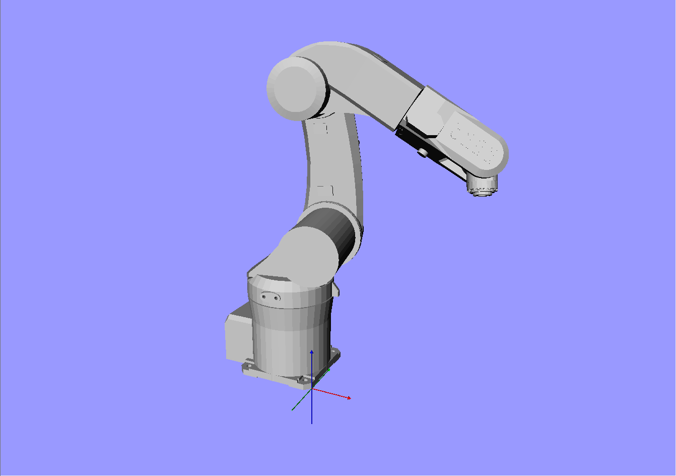
Before you create the scene file, it is important to know the orientation and location of the origin of the coordinate system of your robot model. For the KUKA KR5 Sixx R850 robot model referred to in this document, the origin is located as shown in figure1 . (This figure shows a part of the robot base only, to make the illustration more clear). Arraykuka_coor.jpg
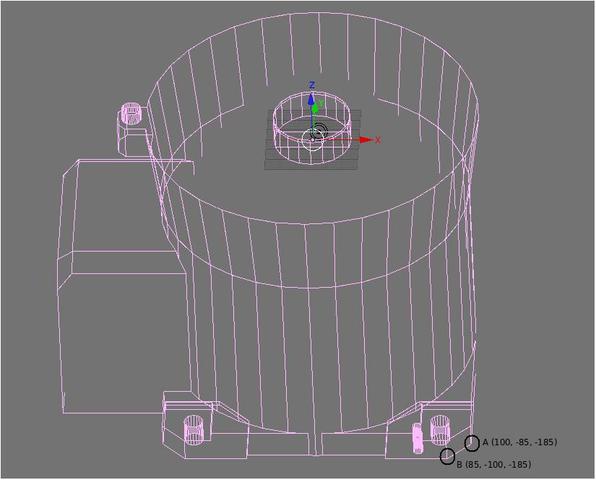
Within this coordinate system, the points A and B at the edge of the robot base have coordinates as shown in figure1 . When the robot model is inserted into the scene description, this coordinate system will be the global coordinate system for the scene description. However, it is not very convenient to have the origin of the global coordinate system at a physically inaccessible point inside the robot's base. Hence, when adding the robot to the scene description, we will translate it such that the global coordinate system is located at the (more physically accessible) point A (it could just as well be at point B, or at any other point whose coordinates are known).

Creating the scene file

  1. Open an empty text document using your favourite text editor. Save it with a .iv extension. For example, mykukascene.iv
  2. Since the scene description is an Open Inventor file, the first line must be
    #Inventor V2.0 ascii
  3. Comments can be added using a #at the start of a file
    #Inventor V2.0 ascii 
    # This is a comment
    # Scene file with kuka robot and 3 obstacles
    
  4. Add lines describing the kuka robot
    DEF robot mpkRobot {
    fileName "kuka.rob"
    }
    

    The file kuka.rob contains a model of the kuka robot. This file is provided for you in the Sarathi distribution.

  5. If we add the robot as described above, the global coordinate system is located at a physically inaccessible point within the base of the robot, as shown in figure1 . To shift the location of the global coordinate system to point A, we add a line specifying a translation of the robot. Our revised lines describing the kuka robot are
    DEF robot mpkRobot {
    fileName "kuka.rob"
    translation -100 85 185
    }
    

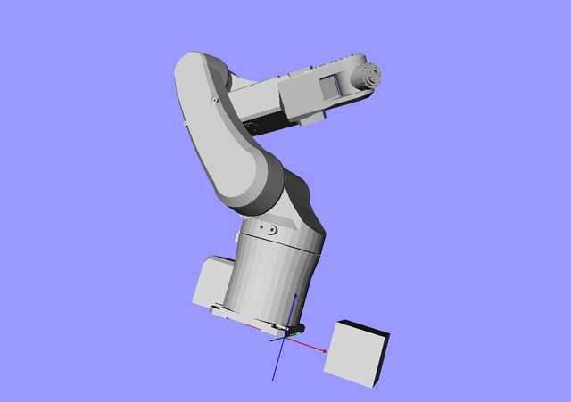
    We are moving the robot with respect to the global coordinate system, which is now effectively at the point A. See figure2 Array

  • We now add obstacles using mpkObstacle. An obstacle can be any Open Inventor object node type. We will add a cube with parameters width=height=depth=120mm. (Note that the openinventor Cube type doesn't have to be a geometric cube. This means that the width, height and depth parameters need not be equal to each other.) By default, the cube is created such that it is centered at the origin of the global coordinate system. Let us position our cube such that it is 150mm away from the origin of the global coordinate system along the X- and Y- directions.
    DEF box mpkObstacle {
        Separator {
            Translation {translation 150 150 0}
            DEF __triangulate__ Cube {
                width 120
                height 120
                depth 120
                }
            }
    }
    

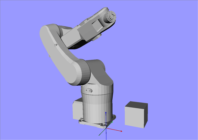
    The 'DEF __triangulate__' tag is required to tell MPK that the triangles of the Cube node are part of the collision model. Similarly, one could add other Inventor models inside the same mpkObstacle node. Without the 'DEF __triangulate__' tag, the models would be displayed but will not be checked for collisions. The syntax for translation is: Translation {translate x y z} where x,y and z refer to translation distances along those axes. Consecuting translation transforms are concatenated. The result of the above obstacle addition is shown in figure3 .Array

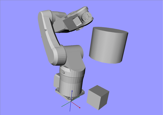
  • Notice how the cube appears to go below the plane of the robot base in figure3 . This is because, the cube is, by default, centered at the origin of the global coordinate system. We merely translated it along the X- and Y- axes in the previous step. To make the cube base coplanar with the robot base, we need to translate it upwards (along the positive Z- axis in this case) by half its height. Thus, we change the translation parameters line to: Translation {translation 150 150 60}. The result is shown in figure4 .Array
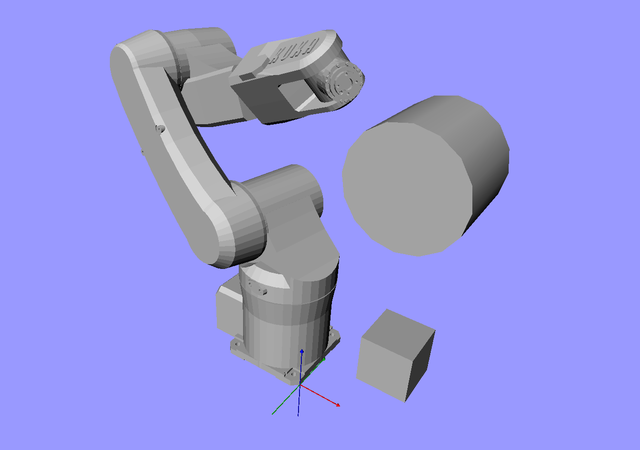
  • We will now add a cylindrical obstacle. By default, Open Inventor adds a cylindrical obstacle such that it is centered at the origin of the global coordinate system and its axis is aligned with the Y axis. (Ignore the commented line. It is explained in the next step.)
    DEF cyl mpkObstacle {
        Separator {
            Translation {translation 150 150 500}
    #       Rotation {rotation 1 0 0 -1.57}
            DEF __triangulate__ Cylinder {
                parts   ALL
                radius  120
                height  200
                }
            }
    }
    

    The result is shown in figure5 .Array

  • What if we want to rotate the cylinder by 90 degrees? Rotations are specified by a line like: Rotation rotation {x y z angle}, where one of x,y or z must be 1, indicating the axis around which rotation should take place. angle is specified in radian. Consecutive rotation transforms are concatenated. So to rotate the cylinder about the X- axis by -90 degrees, just uncomment the Rotation… line in the code above. The result is shown in figure6 .Array
  • Now let us put the robot on a table. We will consider a table to be an open inventor “Cube” with relatively large dimensions along two axes (length and width) and a very small dimension along the third axis (the thickness). We can add it similar to the way we added the Cube previously. However, this time we do things a bit differently. Assume that the table is described in a file called “table.iv”.
    DEF table mpkObstacle {
        Separator {
            Scale {scaleFactor 1 1 1}
            DEF __triangulate__ File {name "table.iv"}
        }
    }
    

    Note that the Scale {scaleFactor 1 1 1} line has no effect here, since it just scales the table by a factor of 1 along all axes. It is included here to show the possibility of scaling the object being included. The table.iv file is simply contains

    #Inventor V2.0 ascii
    Separator {
            Translation {translation 0 0 -5}
            Cube {
                width 1200
                height 1200
                depth 10
            }
    }
    

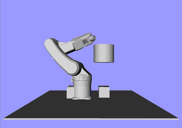
    The result is shown in figure7 .Array

  • Appendix

    The complete scene description file we have created is given below.

    #Inventor V2.0 ascii
    #Scene file with KUKA robot and 3 obstacles
    DEF robot mpkRobot {
        fileName "kuka.rob"
        translation -100 85 185
    #    rotation 1 0 0 -1.57
    }
    
    DEF box mpkObstacle {
        Separator {
            Translation {translation 150 150 60}
            DEF __triangulate__ Cube {
                width 120
                height 120
                depth 120
                }
            }
    }
    
    DEF cyl mpkObstacle {
        Separator {
            Translation {translation 150 150 500}
            Rotation {rotation 1 0 0 -1.57}
            DEF __triangulate__ Cylinder {
                parts   ALL
                radius  120
                height  200
                }
            }
    }
    
    DEF table mpkObstacle {
        Separator {
            Scale {scaleFactor 1 1 1}
            DEF __triangulate__ File {name "table.iv"}
        }
    }
    

    References

    1. Motion Planning Kit scene documentation
    2. The Inventor Mentor, Chapter 11