Creating robot models for the MPK path planner
Author: Sagar Behere Email: [email protected]
This document summarizes the steps I took to create a robot model for the 6 DOF KUKA KR5 Sixx R850 robotic arm.
Introduction
Robot models for use with the MPK library need to have a “collision model” in Open Inventor's .iv file format. These collision models are basically .iv models of individual robot links. The robot definition ( .rob ) file contains parameters needed to “assemble” the link models into the entire robot arm. The process of generating a suitable link model in .iv format and finding the “assembly” parameters is not immediately obvious. This document describes the steps I had to take to build a .rob file for my robotic arm.
Quickstart
- Generate CAD model of individual links
- Open each model in blender 3d. Save it in blender format.
- Shift origin of global coordinate system of each link to the point about which the link rotates
- Export model obtained in step 3 to .iv format
- Use blender to calculate offsets of coordinate system origin of each link from coordinate system origin of previous link.
Detailed steps
- Download a CAD model of the robot from KUKA website in .STL format
- Import the model into blender. I used version 2.48a
- Go to edit mode, select all vertices ('A' key), set the limit to 0 and remove doubles. This step makes it easier to select parts of the model which need to be deleted later. Also, it could lead to a smaller .iv format representation (less vertices)
- Now, we need models for the individual links. Decide which link is needed and the delete all other parts of the model. Save the file as a .blend file. Next, export it to the .iv format. View the resulting .iv file with the ivview program.
- Repeat step 4 until you have .blend and .iv files for all links.
- If you followed exactly the same steps while generating the link models for all links, the resulting .iv file models will be to scale and the individual link models will be positioned at the right places. This means that if you collect together all the .iv link models in a single .iv file (see box to see how), you'll see the entire robot arm with all the links in their right places.
#Inventor V2.1 ascii #robot model Separator { File {name "kuka_0.iv"} File {name "kuka_1.iv"} File {name "kuka_2.iv"} File {name "kuka_3.iv"} File {name "kuka_4.iv"} File {name "kuka_5.iv"} File {name "kuka_6.iv"} } - Next, we need to mess with the link models in order to position the local coordinate system (in the exported .iv files) at the right point and orientation. This is important because in the robot definition files, the joint rotations are specified around the axes of the local coordinate system. Unless the local coordinate system is in the right place in each link model, your robot links will go all over the place when you use the .rob file in MPK
- The local coordinate system in the exported .iv file matches the global coordinate system in blender. Thus, you need to move the global coordinate system to that point on a link, about which the link rotates, when connected to the previous link. See figure1 to see where I had to position the global coordinate system for each link of my robot. Once you have shifted the global coordinate system to the right place, save the .blend model and export it to .iv format again. Array
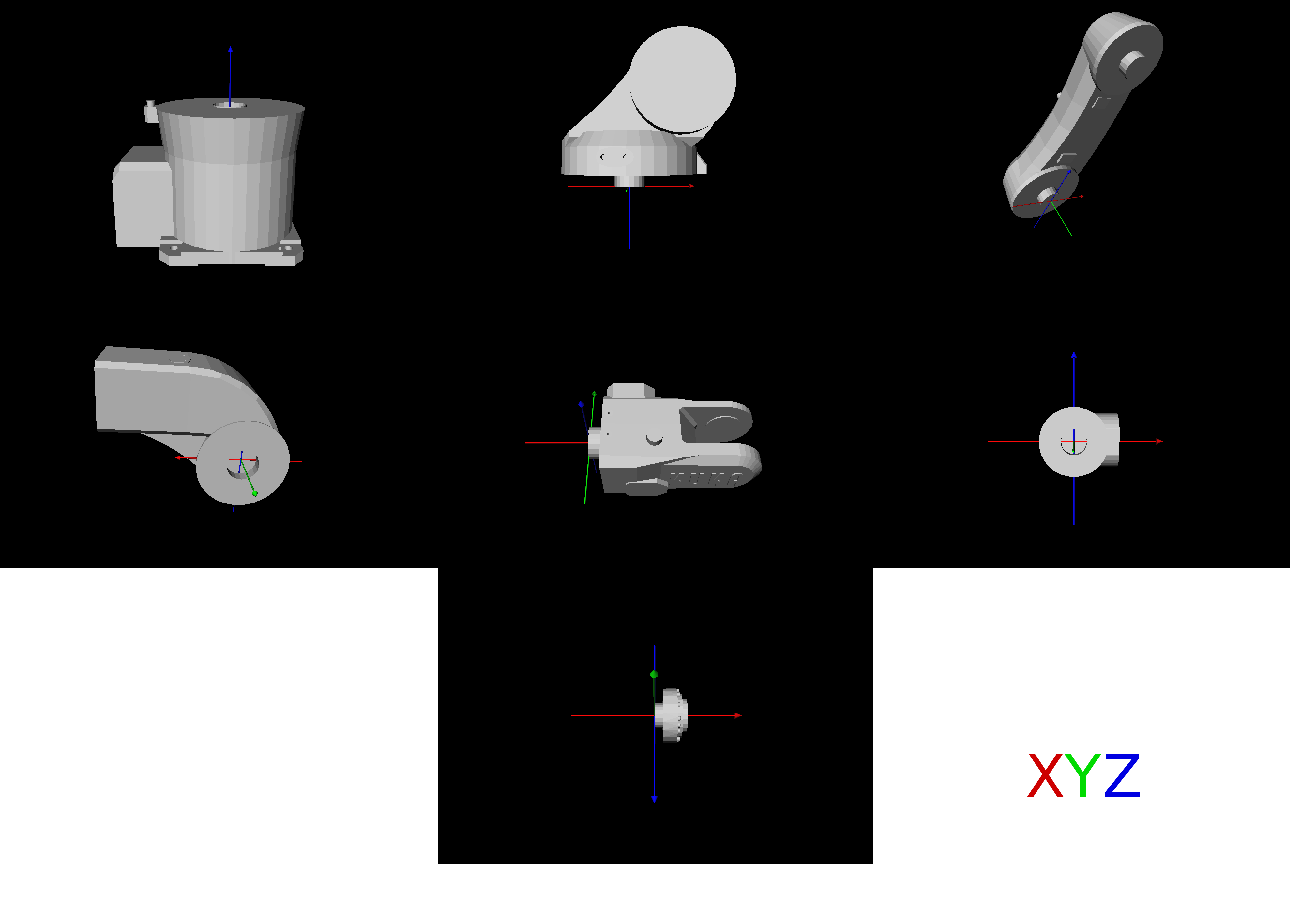 Fig. 1: Link models

Now, if you use the code given in the box above to collect the links together into a robot model, its not going to work. This is because inventor will place all the links such that the origins of their local coordinate system coincide. You need to specify the offset of the origin of the coordinate system of each link, from the origin of the coordinate system of the previous link. For example, lets say we need to find the offset of link 3 w.r.t link 2. To do this, open the .blend model of link 2. Zoom in to the point on the link, where link 3's coordinate system origin will touch, when it is properly assembled. Get the coordinates of this point. These will be the offset of link 3 w.r.t link 2. Note this data carefully. You'll need it to build the .rob
file.
Repeat the steps of point 9 till you know the offset of each link w.r.t its previous link.
Array
Fig. 2:
The assembled KUKA robot